
OPMP
Detect Failures Before They Become Downtime
ECEMTAG combines powertrain domain knowledge, vehicle data acquisition and edge intelligence to monitor equipment health directly where the data is generated.
Unexpected failures are scheduled rather than condition-based servicing.
Disconnected vehicles/machines
Large raw datasets
Cloud/security restrictions
ECEMTAG approach
Acquire → Analyse → Detect → Predict → Validate
Your platform work explicitly includes fault classification, anomaly detection, health monitoring and diagnostic data storage.
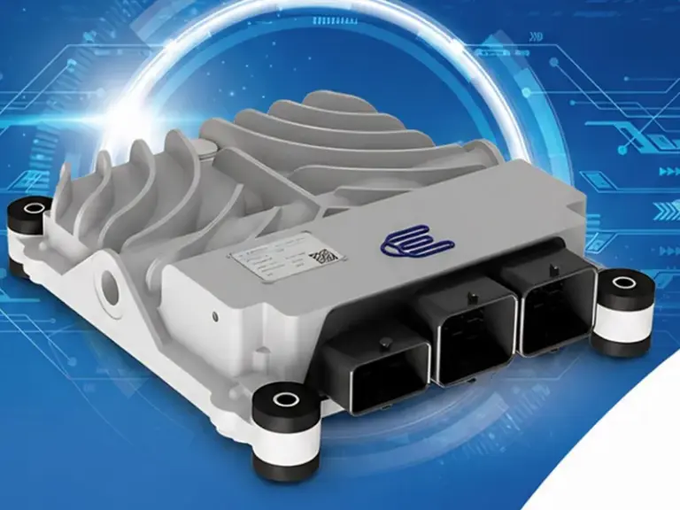
The OCP6000 is a single hardware and software platform for different control applications. The application is developed rapidly with model-based design tools, and the ready-made base software supports diagnostics and calibration. It is designed for automotive, maritime, rail and defence applications.
- Fully compatible with model-based design.
- Design suitable up to ASIL-B level.
- Production-ready open hardware.
- -40 … +105 °C operation, IP69K protection.
Product Brochure
TECHNICAL SPECIFICATIONS
| CORE PROCESSING | |
| Processor | MPC5777C |
| Clock Rate | 300 MHz |
| Flash Memory | 8 MB |
| SRAM | 512 KB on-chip SRAM (incl. 64 KB standby RAM) |
| RTC | Yes |
| COMMUNICATION | |
| CAN Bus | 3 x CAN, ISO/DIS 11898, SAE J1939, XCP |
| DIGITAL INPUTS | |
| Digital Input Pins | 10 x configurable, 6 x short-to-GND |
| POWER | |
| Supply Voltage | 16 … 33 VDC |
| ANALOG INPUTS & SENSORS | |
| Analog Input Resolution | 16-bit |
| Analog Input Pins | 15 x 0 … 5 VDC, < 20 mA, < 20 Hz, 0 … 5 V ratiometric |
| Sensor Supplies | 2 x 300 mA, 5 VDC |
| NTC Sensor Inputs | 4 x 50 Ω … 50 kΩ, configurable |
| PT Sensor Inputs | 7 x 800 Ω … 1800 Ω, configurable |
| Voltage Inputs | 4 x 0 … 33 V |
| LOW-SIDE OUTPUTS | |
| Injector Outputs | 6 x peak & hold (25 A peak / 15 A hold), configurable |
| GP / PWM Outputs | 2 x 2.7 A, 24 VDC with monitoring and diagnostic; 8 x 1.5 A, 24 VDC with monitoring and diagnostic; 2 x 3 A, 24 VDC with diagnostic |
| HIGH-SIDE OUTPUTS | |
| Injector Outputs | 2 x bank, boost/hold 48 V / < 25 A / T < 1 ms, 24 V / < 15 A / T < 5 ms; 48 V generation, current control, second switch ability |
| GP / PWM Outputs | 12 x 3 A, 24 VDC with monitoring; 8 x 1 A, 24 VDC with monitoring |
| LAMP OUTPUT | |
| Lamp Output | 10 x configurable, 6 x short-to-GND |
| INTERNAL FEATURES | |
| Injector Bank Supply | 10 x configurable, 6 x short-to-GND |
| MECHANICAL & ENVIRONMENTAL | |
| Dimensions | 220 x 247 x 57 mm (W x L x H) |
| Material | Aluminum |
| Operation Temperature | -40 … +105 °C (with active cooling) |
| Mounting | 4 x M7 bolt |
| Weight | 2.5 ± 0.5 kg |
| Connectors | Molex CMC 154-pin, 3-pocket |
| Vibration | DIN EN 60068-2-6 |
| Environmental Protection | IP69K |
| Location | Engine compartment / chassis |
| COMPLIANCE & STANDARDS | |
| CISPR 25 | Conducted and radiated emissions compliance |
| DIN EN 11452-4 | Level 2, 150 kHz – 400 MHz |
| DIN EN 11452-2 | Level 2, 200 MHz – 3.2 GHz; AM: 200 – 800 MHz, PM: 800 MHz – 3 GHz |
| DIN EN 55025 (Ch. 6.2) | Class 3, 150 kHz – 108 MHz |
| DIN EN 55025 (Ch. 6.4) | Class 3, 150 kHz – 2.5 GHz; horizontal and vertical polarization |
| DIN EN 10605 (Ch. 9) | ESD: ±8 kV contact |
| ISO 16750-2 Withstand Voltage | Electrical loads up to 58 V |
| ISO 16750-2 Starting Profile | US6: 6 V, UA: 6.5 V |
| ISO 16750-2 Load Dump | US*: 58 V |
| MIL-STD-1275E | Sections 4.1, 5.1.1.1, 5.1.2, 5.1.1.2, 5.1.3.1.2 |